[嵌入式开发模块]AD转换芯片ADS8344驱动模块
文章目录
- 芯片简介
- 代码
- 头文件
- 源文件
- 使用及示例代码
芯片简介
ADS8344是一个8通道16位模数转换器,使用SPI接口。
其可以使用单端或差分输入,单端模式时,每个CHX独立作为采样输入,测其相对于模拟地的差值。差分模式时,CH0和CH1、CH2和CH3……分别作为一组,测两者之间的差值(前者为正)。
采样值是一个16位无符号整型,0对应着模拟地(以及更低),65535(最大值)对应着参考电压Vref(以及更高),中间值则将模拟地和参考电压间的电压值平分。
比如要是要是COM接着的是0V,Vref接着5V,而采样值测出为34532,那么实际测量到的电压= (5V - 0V)/65535*34532 + 0V ≈ 2.63V
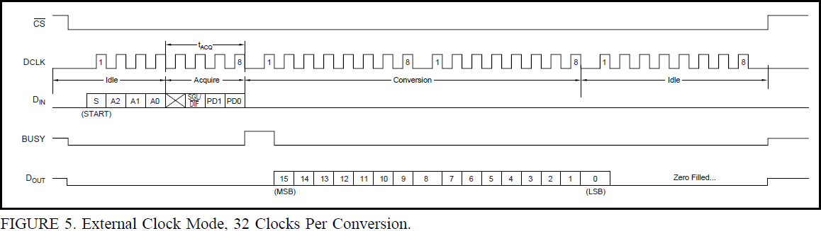
通信方式对应于时钟分为多种: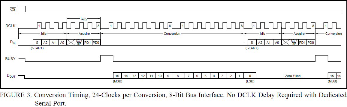
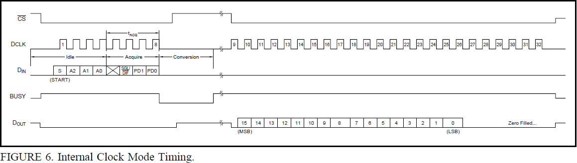
概括来说,CS引脚断言后,芯片会以收到的第一个1作为控制字节的开始,收完控制字节后开始转换,转换中BUSY引脚会变化,然后根据选择的模式会略有不同。
这里,驱动使用了外部时钟模式,这种模式下,一次转换需要最少25个时钟周期,去掉控制字节的8个,就是17个时钟周期。这是应该控制字节后的第一个时钟周期是用于转换的,第二个时钟周期才开始传输结果。因为大部分单片机都是以字节为单位进行通信的,因此一次转换就需要32个时钟周期。最后7个bit会被填充0,真正的数据是倒数第8个bit起,往前16个bit。
因为十分直白明了,就介绍到这了,代码也不多。
代码
头文件
/******************************************************************************************* ADS8344 DRIVER MODULE* ADS8344驱动模块** File : ADS8344.h* By : Lin Shijun(http://blog.csdn.net/lin_strong)* Date : 2019/04/28* Version : V1.0* Note : It only support Single-Ended Channel and external clock mode in this version.* To use the interface:* a. register the SPI functions to the module by regFuncSPI and regFuncCS.* b. call sampleChannelSGLEXT to get one sample at specified channel.* Note that the return value of sample is a uint16_t type. 0 means the input* equal to or lower than GND, 65535 means equal to or higher than Vref.* For example, assume that GND is 0V, Vref is 5V, sample result is 34532, than* input = (5V - 0V)/65535*34532 + 0V = 2.63V*****************************************************************************************/#ifndef _ADS8344_H#define _ADS8344_H/****************************************************************************************** INCLUDES*****************************************************************************************/#include <stdint.h>/****************************************************************************************** CONSTANTS*****************************************************************************************/// Single-Ended Channel Selection // A2 A1 A0#define ADS8344SGL_CH0 0 // 0 0 0#define ADS8344SGL_CH1 4 // 1 0 0#define ADS8344SGL_CH2 1 // 0 0 1#define ADS8344SGL_CH3 5 // 1 0 1#define ADS8344SGL_CH4 2 // 0 1 0#define ADS8344SGL_CH5 6 // 1 1 0#define ADS8344SGL_CH6 3 // 0 1 1#define ADS8344SGL_CH7 7 // 1 1 1// Differential Channel Control // A2 A1 A0#define ADS8344DIF_CH0 0 // 0 0 0#define ADS8344DIF_CH2 1 // 0 0 1#define ADS8344DIF_CH4 2 // 0 1 0#define ADS8344DIF_CH6 3 // 0 1 1// Power-Down Selection.// Power-down between conversions. When each conversion is finished, the converter enters a// low-power mode. At the start of the next conversion, the device instantly powers up to// full power. There is no need for additional delays to assure full operation and the very// first conversion is valid.#define ADS8344PD_Powerdown 0// Selects Internal Clock Mode.#define ADS8344PD_InternalClk 2// No power-down between conversions, device always powered. Selects external clock mode.#define ADS8344PD_ExternalClk 3/****************************************************************************************** INTERFACES*****************************************************************************************/// description: Register SPI call back functions// parameter : spi_rb callback function to read byte using SPI(keep MOSI low!!!!!)// spi_wb callback function to write byte using SPI// return :// note : you should register SPI functions through this interface before use the driver.void ADS8344_regFuncSPI(uint8_t (*spi_rb)(void), void (*spi_wb)(uint8_t wb));// description: Registers call back function for ADS8344 select & deselect.// parameter : cs_sel callback function for ADS8344 select// cs_desel callback fucntion for ADS8344 deselect// return :// note : you should register CS functions through this interface before use the driver.void ADS8344_regFuncCS(void(*cs_sel)(void), void(*cs_desel)(void));// description: sample the channel 'ch' with Single-Ended Channel and external clock mode.// parameter : ch the channel to sample, see ADS8344SGL_CHX// return : the sample result.// note :uint16_t ADS8344_sampleChannelSGLEXT(uint8_t ch);#endif
源文件
/******************************************************************************************* ADS8344 DRIVER MODULE* ADS8344驱动模块** File : ADS8344.c* By : Lin Shijun(http://blog.csdn.net/lin_strong)* Date : 2019/04/28* Version : V1.0* Note :*****************************************************************************************//****************************************************************************************** INCLUDES*****************************************************************************************/#include "ADS8344.h"/****************************************************************************************** CONSTANTS*****************************************************************************************/#define ADS8344MASK_S 0x80#define ADS8344MASK_SGL 0x04/****************************************************************************************** LOVAL OBJECTS*****************************************************************************************/static uint8_t _spi_rb_default(void){return 0;}static void _spi_wb_default(uint8_t wb){(void)wb;}static void _nullFunc(void){}static uint8_t (*_spiRead)(void) = _spi_rb_default;static void (*_spiWrite)(uint8_t wb) = _spi_wb_default;static void(*_csSel)(void) = _nullFunc;static void(*_csDesel)(void) = _nullFunc;/****************************************************************************************** INTERFACE IMPLEMENTATIONS*****************************************************************************************/void ADS8344_regFuncSPI(uint8_t (*spi_rb)(void), void (*spi_wb)(uint8_t wb)){_spiRead = spi_rb;_spiWrite = spi_wb;}void ADS8344_regFuncCS(void(*cs_sel)(void), void(*cs_desel)(void)){_csSel = cs_sel;_csDesel = cs_desel;}uint16_t ADS8344_sampleChannelSGLEXT(uint8_t ch){uint16_t ret;_csSel();// write control byte_spiWrite(ADS8344MASK_S | (ch << 4) | ADS8344MASK_SGL | ADS8344PD_ExternalClk);ret = _spiRead() << 8;ret |= _spiRead();ret <<= 1;ret |= (_spiRead() >> 7);_csDesel();return ret;}
单元测试代码就不放了。
使用及示例代码
没多少代码,很简单的一个模块。
使用的步骤就是,先按要求实现SPI相关接口并进行注册,让模块知道怎么调用SPI。然后再使用ADS8344_sampleChannelSGLEXT接口获得采样值就行了。
#include <stdio.h>#include "SPI.h"#include "ADS8344.h"// 已隐去不重要部分#define ADS8344_SPI SPI2#define ADS8344_CSDDR DDRH_DDRH7#define ADS8344_CS PTH_PTH7static void Delay(void);static void INIT_PLL(void);static uint8_t ADS8344_readByte(void){return SPI_ExchangeChar(ADS8344_SPI, 0x00);}static void ADS8344_writeByte(uint8_t b){SPI_ExchangeChar(ADS8344_SPI, b);}static void ADS8344_SelectCS(void){ADS8344_CS = 0;}static void ADS8344_DeselectCS(void){ADS8344_CS = 1;}void main(void) {// 已隐去不重要部分ADS8344_CSDDR = 1;MODRR_MODRR6 = 1; // route the SPI2 to port H// 初始化SPI(void)SPI_Init(ADS8344_SPI);(void)SPI_Enable(ADS8344_SPI);// 注册SPI相关接口给模块使用ADS8344_regFuncSPI(ADS8344_readByte,ADS8344_writeByte);ADS8344_regFuncCS(ADS8344_SelectCS,ADS8344_DeselectCS);for(;;) {Delay();// 采样一次通道CH1并打印printf("%5u\r\n", ADS8344_sampleChannelSGLEXT(ADS8344SGL_CH1));}}


还没有评论,来说两句吧...